- Home | Pentair Food & Beverage Solutions
- Products
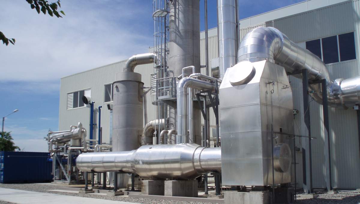
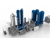
- Advanced Amine Technology Carbon Capture Plants - AAT
Carbon Capture FOR lOW co2 cONCENTRATION sOURCES
Pentair Advanced Amine Technology with live industry-tested solvents enables businesses to capture and extract value from their CO2 by-product.
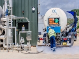
By capturing CO2 from flue gas sources such as steam boilers, natural gas-fired combustion engines, and non-power generation sources, you can produce high-quality CO2 that meets food-grade standards. The purified liquid CO2 has a purity rate exceeding 99.999% and can be used, for example, to carbonate beverages and enable soft drink producers to become CO2 self-sufficient or to sell as a commercial opportunity.
Benefits
- Durable plant design can withstand high oxygen (O2) concentrations of up to 15% in the flue gas.
- Ability to extract CO2 from numerous flue gas sources with high O2 concentrations. References range from gas turbines to lime kilns, ranging from 3-25% of CO2 concentrations.
- More efficiencies in CO2 absorption capability due to higher amine concentration.
- Benefit from a lower OPEX in the CO2 extraction process due to reduced heat consumption.
- Patented design can eliminate the need for heat sources such as steam (if hot flue gas is available).
- Flexibility with non-licensed amine – available worldwide.
- Engineered-to-order plant ensures optimal customer-specified design for a specific gas source.
-
Functional Description
-
- Pentair Advanced Amine CO2 Capture Plant relies on absorption technology, which employs concentrated monoethanolamine (MEA) to react with the carbon dioxide (CO2) and extract it from the gas stream.
- After capturing the CO2 in the MEA solution, it is transferred to the stripping (deabsorber) unit. In this unit, the solution’s temperature is raised to reverse the chemical reaction that occurred during absorption, thereby releasing the CO2 from the MEA solution. The gas being released from the stripper is a highly concentrated stream containing roughly 99% pure CO2.
- This concentrated stream can be used in its gaseous form or further purified and liquefied to meet the standards for food and beverage-grade CO2 specified by regulators. Purification is the final step, consisting of a compression, drying, and liquefaction process, increasing the purity to food-grade and Northern Lights specification (99.999% (v/v)).
- Pentair Advanced Amine CO2 Capture Plant relies on absorption technology, which employs concentrated monoethanolamine (MEA) to react with the carbon dioxide (CO2) and extract it from the gas stream.
-
Features
-
- Pentair patented component, NOxFlash, and highly concentrated amine (monoethanolamine - MEA) allow for high oxygen, O2, concentrations in the flue gas.
- Patented design Pentair flue gas heated reboiler efficiently utilizes heat from flue gas, eliminating the need for steam.
- NOxFlash efficiently removes nitrogen dioxide, NO2, resulting in a high purity CO2 and reducing degradation of amine.
- Pentair Amine Systems are designed to produce food-grade quality CO2, as per ISBT and EIGA specifications.
- Plant traditional sizes (measured as liquid food-grade CO2 produced): 500 - 4500 kg/h. Other capacities are available upon request.
- Pentair patented component, NOxFlash, and highly concentrated amine (monoethanolamine - MEA) allow for high oxygen, O2, concentrations in the flue gas.
DOWNLOADS
| Title | Download PDF | |
| Product leaflet | Union Engineering Advanced Amine Technology - AAT | Download |
| Technical documentation | Looking for operating instructions, installation manual, spare part list etc.? | Please, send us your request |
Related products
UNION ENGINEERING CO2 EXTRACTION PLANTS FOR BOILER SYSTEMS - EXTRACTION BASED UNIT - EBU
Make a valuable business of imported flue gas from boilers fired with fossil fuels.
The analysis of both commercial and recovered gas - an excellent tool to check the performance of the CO2 Recovery Plant.

UNION ENGINEERING CO2 SELF-GENERATING PLANTS - COMBUSTION BASED UNIT - CBU
Based on the latest technologies, CO2 generating plants (CBU) from Union Engineering meet the strictest CO2 quality requirements.
NEWS